This laboratory was made possible by generous support from Keysight Technologies. Cutting edge RF measurement equipment and resources were donated to U.C. Berkeley to enhance RF and Microwave education at the undergraduate level.
Laboratory
Each lab experiment involves reading related to the course material, a pre-lab, the actual lab construction and measurements, and a post lab write-up. The lab is designed to reinforce the material from the lecture and to delve deeper into practical issues that can only be acquired through careful experimentation.
Many thanks to the people who have worked hard to improve the labs. In particular, thanks to Dr. Joel Dunsmore who co-created these labs during his semester at Berekley. Also many thanks to Anita Flynn for "hardening" the labs, especially for her efforts on creating "lab 0".
| Lab 0: | Introduction to Keysight ADS | |
| Stop ! | Care of Expensive Equipment | Exam |
| Lab 1 | Calibration Network Analyzers / Tools and Tips for RF Electronics | |
| Lab 2 | High Frequency Components | |
| Lab 3 | LC Filters | |
| Lab 4 | Tuned Amplifiers | |
| Lab 5 | Distortion/Noise/Mixer Measurements | |
| Lab 6 | Noise Measurements | |
| Lab 7 | Mixer Lab | |
| Lab 8 | Power Amplifiers (Bonus) | |
| Lab 9 | Modulation Lab | |
| Lab 10 | Oscillator/VCO Lab (Bonus) |
Resources
| Making your own SMA cables |
| Agilent Precision Connectors |
| Network Analyzer (E5071C) |
| Spectrum Analyzer (vol 1) (vol 2) (E4402B) |
| Vector Signal Generator (N5182a) |
| 2 GHz 20/40 GSa/s Oscilliscope (DS080204B) |
Soldering Tips from Travis.
Wireless Research Instructional Laboratory
A new hands-on laboratory component for EECS 142 has been created. This effort was funded partially by the Vodafone Foundation and Keysight Technologies.
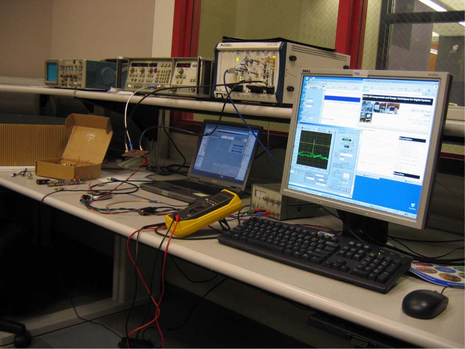
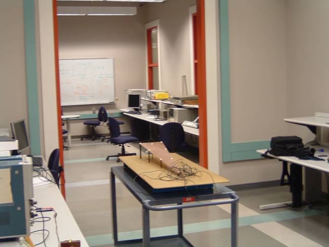
A new laboratory space for undergraduate education related to wireless education has been setup (see above). The lab is equipped with network analyzers, spectrum analyzers, SWR meters, TRL analyzer, antennas, and 900 MHz transceiver building block boards. The transceiver building blocks have been designed, constructed, and tested by an undergraduate team under the supervision of Prof. Niknejad.
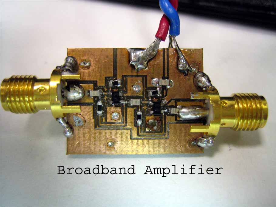
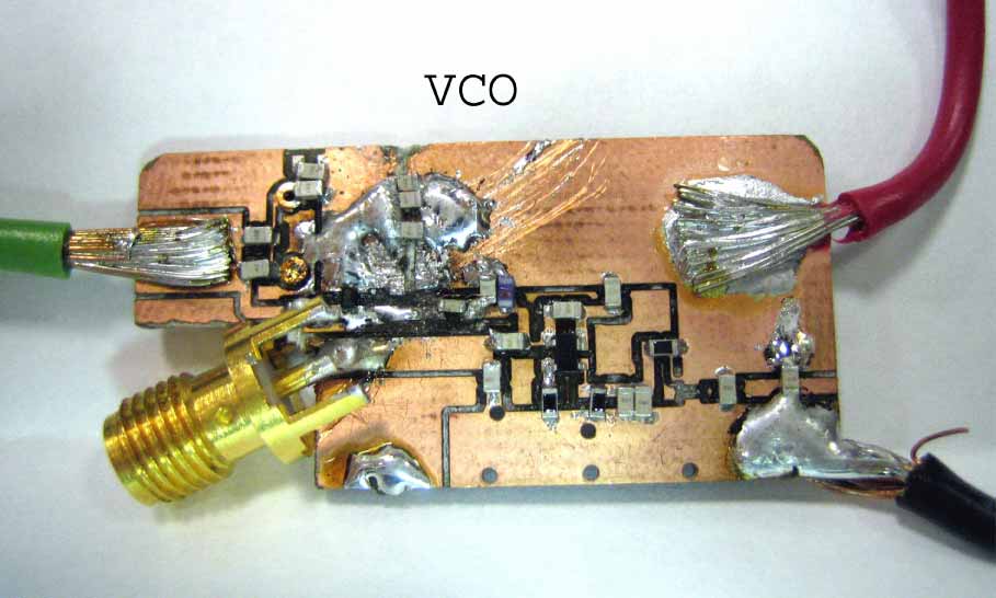
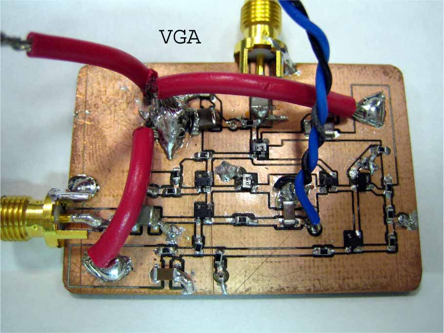
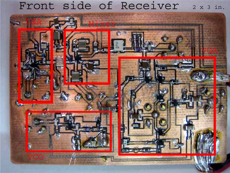
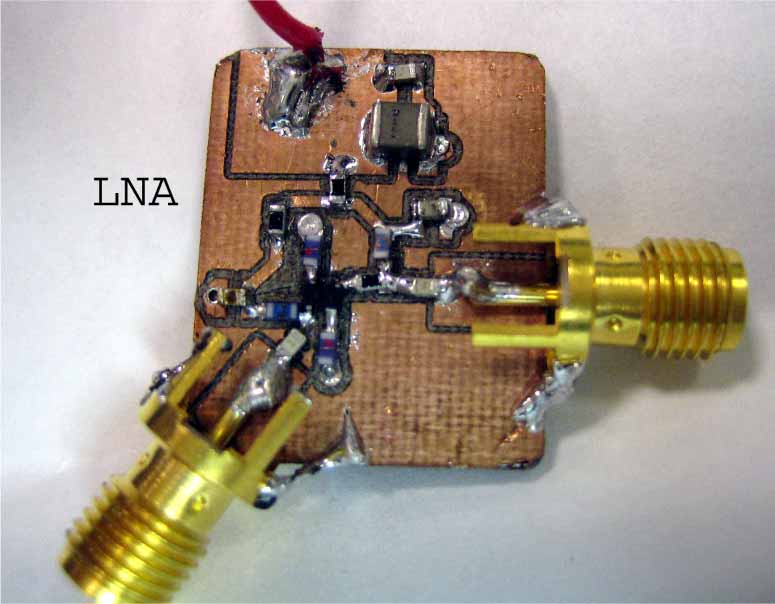
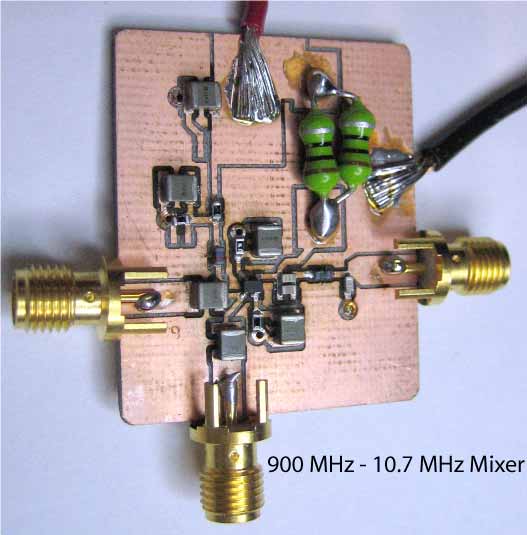
In previous semesters, a prototype single transistor 900 MHz LNA and mixer were designed and shown below. Design of 900 MHz circuits using discrete components (BJT transistors, inductors, capacitors, resistors) using a single layer PCB requires skill typically attributed to "black magic'' RF designers. Students with no previous training in RF design have realized working circuits in the course of one semester. Other blocks, including 900 MHz VCOs, VGAs, and a 100 mW PA have also been constructed and tested.
These blocks were collected to form the simple transceiver shown below. The VCO was custom designed by students, but the PLL is a commercial part. These blocks were tested by students enrolled in the communication IC course using the National Instruments NI5600/5610 software radio. The laboratory projects culminated in wireless transmission of data (a bitmap image file) across the room. Students were exposed to multi-path propagation, equalization, the effect of interference and linearity of the receiver, and other advanced radio and propagation effects.